Product Details
Developed Around the Charging Power Module
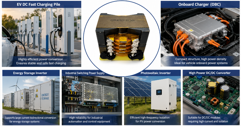
A DC fast charging station does not transfer grid power directly to the vehicle battery. Inside the charger, power electronic modules perform rectification, conversion, isolation and output control before energy reaches the vehicle.
The transformer operates within this power-conversion chain.
Compared with transformers used in low-power electronics, a magnetic component inside a fast charging module must deal with more demanding current, thermal and insulation conditions. This makes core structure, winding arrangement, terminal layout and installation reliability important parts of component selection.
The EE/ER transformer structure shown here is intended for these higher-power conversion environments.
When Charging Current Changes the Transformer Design
Higher charging power increases the electrical and thermal demands placed on the power module.
As current rises, winding conductor losses become more important. Simply increasing the amount of copper is not always sufficient because winding space, heat dissipation, coupling and insulation must still be considered.
A larger EE/ER core arrangement provides additional magnetic and winding space, giving engineers more flexibility when developing transformers for charging power stages.
The final winding arrangement should therefore be based on the actual converter conditions rather than a generic power rating.
Isolation Is Part of the Charging System Design
Electrical isolation is a fundamental consideration in many EV charging power architectures.
The transformer winding structure must provide appropriate separation between circuit sections while still maintaining practical magnetic coupling and thermal performance.
Insulation arrangement, winding spacing and material selection should therefore follow the working voltage and safety requirements of the charging module.
For procurement teams, this means that selecting a charging transformer should involve more than matching input and output voltage.
Built for Large PCB Power Assemblies
High-power charging modules use larger semiconductors, heat sinks, capacitors, bus structures and magnetic components. Mechanical stability becomes increasingly important as component size and weight increase.
This transformer uses a through-hole PCB connection with relatively wide terminal spacing and a reinforced base structure.
Such a configuration provides a stable connection to the power board and is more appropriate for a substantial magnetic component than relying on a lightweight mounting arrangement intended for small electronic circuits.
Thermal Conditions Need to Be Considered at Module Level
Charging equipment can operate for extended periods and may be installed in environments with significant seasonal temperature changes.
Transformer temperature cannot therefore be considered independently from the charging module.
Switching frequency, current, core loss, winding loss, airflow, heat sink arrangement and the temperature inside the charger enclosure all influence operating conditions.
Transformer development should take these system-level factors into account before the final magnetic and winding structure is determined.
Key Specifications & Parameters
Product Name: high frequency transformer for EV DC Fast Charging Module
Product Type: High Power High Frequency Transformer
Core Series: EE / ER Series
Common Core Options: EE55 / EE65 / ER49 and Other Project-Specific Sizes
Core Configuration: Large Magnetic Core / Dual-Core Configuration According to Design
Winding Structure: Multi-Section Layered Winding
Bobbin Structure: Vertical Winding Structure
Mounting Method: PCB Through-Hole Installation
Terminal Layout: Wide-Spaced Terminals for Power PCB Connection
Electrical Design: Developed According to Charging Module Circuit Requirements
Operating Frequency: Determined by Target Converter Architecture
Voltage / Current: Project-Specific
Insulation Structure: Configured According to Working Voltage and Safety Requirements
Target Application: EV DC Fast Charging Power Module

Problems Addressed in Charging Power Design
High Current in the Power Stage
Larger magnetic and winding structures provide additional design flexibility when dealing with substantial current in charging power modules.
Temperature Rise During Extended Charging
Core size, conductor structure and winding arrangement can be selected with continuous operating conditions and module cooling in mind.
Primary-to-Secondary Isolation
The winding system can be developed according to the electrical separation required by the target charging converter.
Mechanical Stress on Large Components
Through-hole terminals and reinforced installation help secure a larger transformer to the power PCB during assembly and operation.
Limited Space Inside Modular Chargers
The magnetic component can be developed around the mechanical envelope of the charger power module rather than using a fixed transformer size.
Different Charging Module Architectures
Core, winding and terminal arrangements can be adapted according to the AC/DC or isolated DC/DC stage in which the transformer is used.
Application Focus
DC Fast Charging Power Module
The primary application is the high-power conversion module inside a DC charging pile. Transformer design can be coordinated with the module's switching circuit, voltage conversion and isolation requirements.
Isolated DC/DC Charging Stage
Where the charger architecture uses an isolated DC/DC stage, the transformer provides energy transfer between electrically separated sections while supporting the required voltage conversion.
Commercial EV Charging Station
Public and commercial charging stations can operate repeatedly throughout the day. Magnetic components used in their power modules therefore need to be considered in terms of long-duration electrical and thermal operation.
Fleet Charging Infrastructure
Fleet depots may operate multiple chargers under frequent charging cycles. Consistent magnetic component construction becomes particularly relevant when identical power modules are produced and maintained at scale.
High-Power Charging Cabinet
Modular charging cabinets may combine several power modules to achieve the required total output. Transformers used within each module need to fit standardized electrical and mechanical conditions to support modular assembly.
Information Needed for Transformer Selection
Instead of selecting an EV charging transformer only by EE55, EE65 or ER49 core size, engineers and buyers should consider:
Charging Architecture: AC/DC or isolated DC/DC stage
Input Voltage: Actual operating input range
Output Requirement: Required voltage and current
Power Module Design: Electrical requirement of each individual module
Switching Frequency: Target operating frequency
Isolation Requirement: Electrical separation and safety requirements
Cooling Conditions: Air cooling and internal module temperature
PCB Space: Maximum footprint and component height
Terminal Requirement: PCB connection and current-carrying considerations
These conditions provide a more useful basis for transformer development than selecting a core model without the surrounding circuit information.
FAQ
Q1: Where is a high frequency transformer used inside a DC fast charger?
It can be used in isolated power-conversion stages within the charging power module. Its exact position and electrical function depend on the AC/DC or DC/DC architecture adopted by the charger manufacturer.
Q2: Why are larger EE/ER cores used for EV charging applications?
Larger core structures provide additional magnetic cross-sectional area and winding space. This can be useful when the transformer must accommodate higher current and more demanding power-conversion conditions.
Q3: Why is current capability important for a charging transformer?
Higher current increases conductor loss and heat generation. Winding conductor size, arrangement, core selection and cooling conditions therefore need to be evaluated together when developing a transformer for a charging module.
Q4: Why does the PCB mounting structure matter in a charging power module?
High-power transformers are physically larger and heavier than many low-power magnetic components. A stable through-hole mounting structure helps secure the component to the PCB and provides practical connections for the power circuit.
Q5: Is EE65 always better than EE55 for a charging transformer?
No. A larger core provides more magnetic and winding capacity, but it also occupies more space. Selection depends on power-stage requirements, switching frequency, current, temperature rise, winding structure and the available mechanical envelope.
Q6: What should a charging equipment manufacturer provide before transformer development?
The most useful information includes circuit topology, input and output conditions, module power requirement, switching frequency, maximum current, isolation requirement, cooling conditions and available PCB dimensions.





 Phone
Phone